This is a an exam. You may consult your notes, any book, and the Internet. You may not speak with any person other than Jeff Ondich, electronically or otherwise, about the content of this exam. If you obtain relevant information from any source other than yourself, cite your sources clearly. Justify your answers. (Note that "justify your answers" implies "show your work.") Have fun.
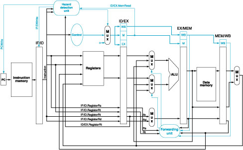
(10 points) Do problems 6.17, 6.18, and 6.19 on page 456 of Patterson and Hennessy. The best justification for your answers would involve a diagram of the relevant datapath, with appropriate labeling and explanation. In any case, don't just give me answers--give me justification as well.
(10 points) Consider the following caches, each of which can hold up to sixty-four 32-bit words of data. Assume that addresses are 32 bits long.
For each of these caches, answer the following questions.
Draw a diagram of the cache. How many bytes of memory does it use?
Suppose the contents of the following addresses are requested in the indicated order:
45, 48, 52, 56, 123, 129, 76, 250, 185, 186, 251, 306, 53, 310
Once this sequence of requests is finished:
Notes: (1) These addresses are byte addresses--so byte 3 is contained in the word starting at address 0. (2) These hit ratios are very low, both because the caches start out empty, and because I have made no effort to make my numbers adhere to the principles of spacial or temporal locality.
(20 points) Building a datapath
Suppose you have an anemometer that reports wind speed as a 16-bit non-negative integer (the leftmost bit is always 0--wasteful, but it will make your job easier, since you'll be able to treat all 16-bit integers as signed), continuously transmitted over a 16-bit line coming from the device. Suppose further that you have a two-character display, capable of displaying any two ASCII characters, represented as 8-bit bytes sent to the display over another 16 wires.
In addition to the anemometer and the display, you have a small machine/assembly-language architecture. It consists of:
Each instruction has the format:
Register R0 takes input from the anemometer (see LOAD below). Register R1's contents are wired directly to the display, so whatever characters you put into R1 appears immediately on the display.
The op-codes are as follows.
Here's an example program, that puts "UP" on the display if the wind speed is rising, and "DN" in the display otherwise. (By "rising," I mean in the most trivial sense--that is, the most recent measurement is higher than the measurement before it--in reality, you would want to write a more sophisticated program.)
Here's your job. Design a datapath and control to implement this machine architecture. Hand in a drawing of the datapath, a chart showing how op-codes would map to control values, and any explanations you deem appropriate.